Photo gallery: a year with the Open Book
Originally published on Patreon.
Last week, a tweet from last May popped up, and it reminded me of something I saw online recently: The Design Squiggle.
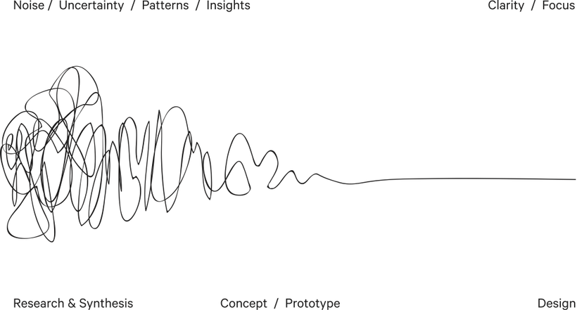
CC BY-ND-3.0: The Process of Design Squiggle by Damien Newman, thedesignsquiggle.com
The drawing describes the journey of the design process, ”of researching, uncovering insights, generating creative concepts, iteration of prototypes and eventually concluding in one single designed solution… Beginning on the left with mess and uncertainty and ending on the right in a single point of focus: the design.”
It’s funny because in my room I have an old Adafruit box on which I’ve scrawled “E-Ink/Reader”, that contains all the squiggles along the way. So a year in, I figured I would share some of them.
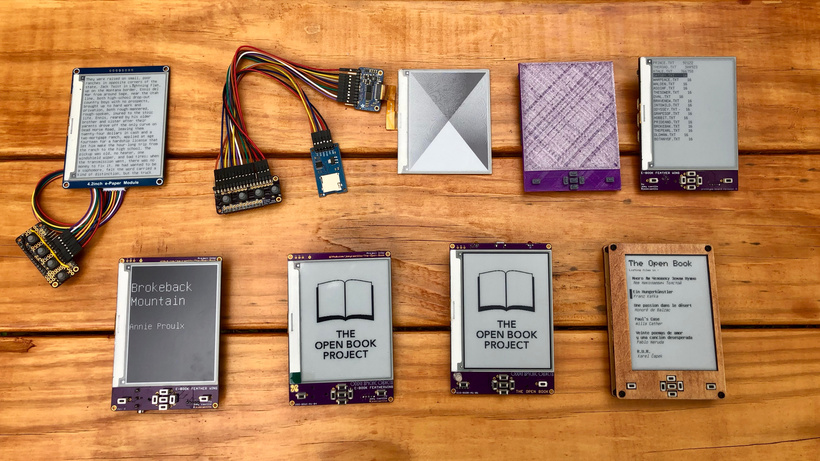
Alas, the first one was lost somewhere along the way. It was that big 3D-printed enclosure from the tweet, with the big 7.5 inch display. Unfortunately that screen never refreshed fast enough to make for a good book-reading experience, plus it was relatively pricey. Pretty soon after that, I moved to the 4.2 inch screen that’s in use now:
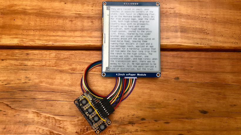
This was hand-soldered, four buttons (I was imagining up, down, left and right in a horizontal row, like the Vim direction keys). But after burning a whole lot of plastic with my soldering iron, I decided I needed to learn a bit of PCB design.
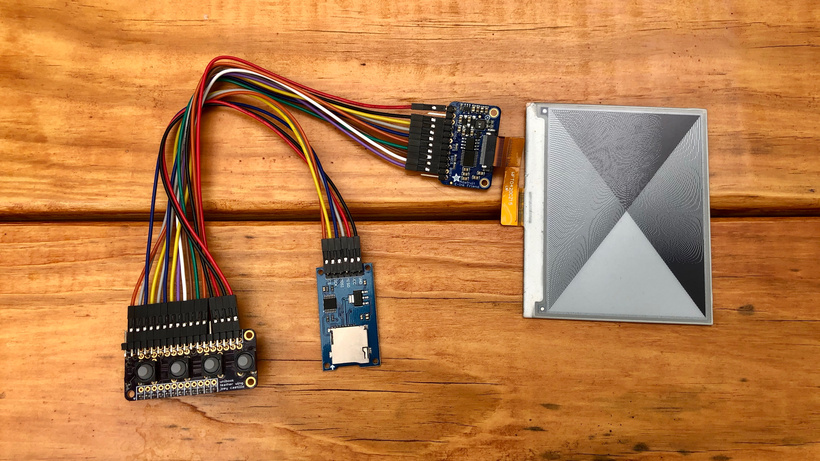
That left bit was the first PCB I ever designed, and in hindsight, it’s funny to think of how little I knew back then. I just took the protoboard I was using, deleted the holes that I wasn’t using, and connected the buttons and pins with traces. There wasn’t even a working schematic behind it. But it worked, and it also let me break out pins for an SD card.
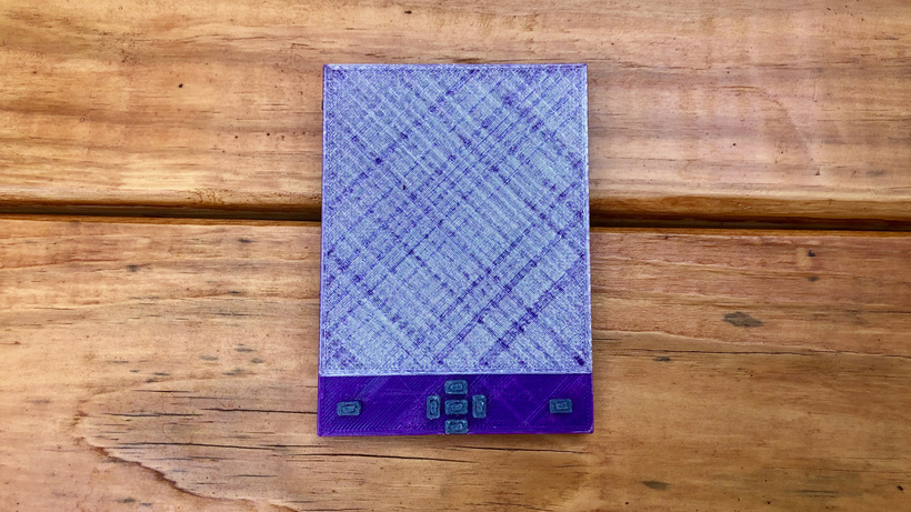
After that, I started to settle in to a form factor that I wanted to build: seven buttons on the front (a directional pad and previous/next buttons), a Lock button, and two buttons for previous and next on the sides. But I wasn’t confident enough about designing the PCB without feeling it in my hand, so I used my 3-D printer to make this plastic prototype.
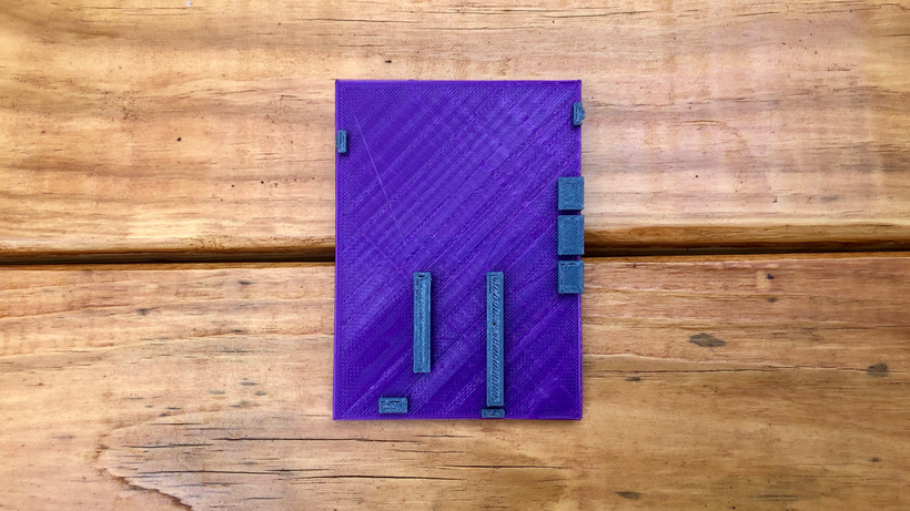
Also, since I’d been using a Feather to prototype, I knew there were enough pins on a Feather header to do the things I wanted to do, so I included the FeatherWing headers on the prototype. At the time I’d also just gotten an Adafruit PyBadge, and I loved the trio of STEMMA ports along the bottom side; the idea that I could have an extensible e-book reader, with ports for a reading light or a sensor of some kind. So those are on here too.
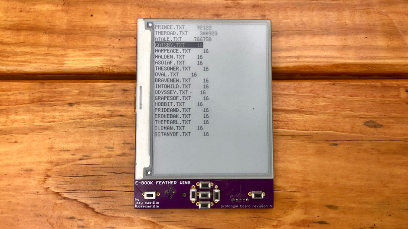
This was the first E-Book Wing prototype. It had some issues. I didn’t fully understand the e-ink power supply circuit, which led to it just displaying gray static whenever I tried to display a page of text.
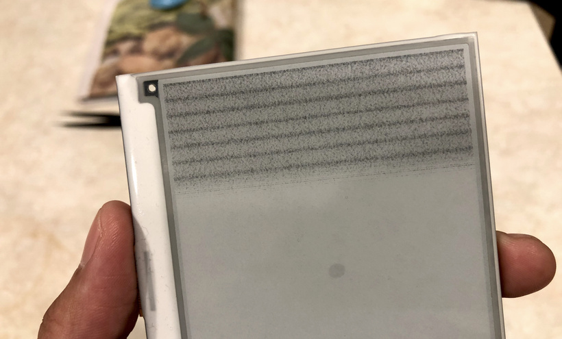
Not going to lie, this led to a lost month despairing over the fear that I was in over my head. Eventually, I asked for help, and Tom Fleet (who I didn’t know other than as a friendly person on Twitter) looked at the schematic and made a suggestion; four cut traces and two bodge wires later, it worked!
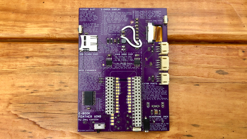
Another issue was that the screen didn’t fit perfectly on the PCB, which made it very fragile if dropped. And the headphone jack was the wrong size (2.5mm instead of 3mm). So there was another revision.
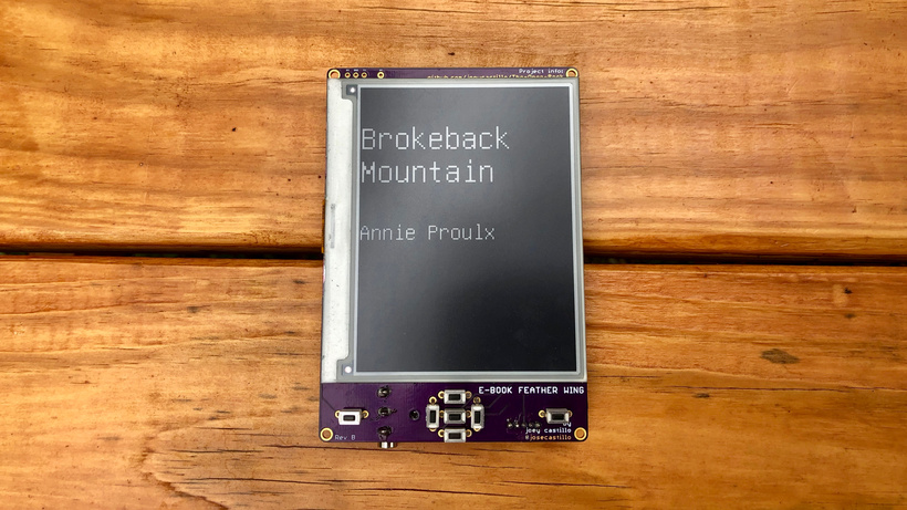
This was the moment that it really felt like the design was taking shape. I added mounting holes, for fitting it into an eventual enclosure, and while some of the text was misaligned and the headphone jack was comically oversized, this one worked. (Brokeback Mountain, incidentally, is the first story I read on the E-Book Wing; I picked it because it’s a lovely read, the text is on the New Yorker’s web site, and it’s short enough to read in one sitting.)
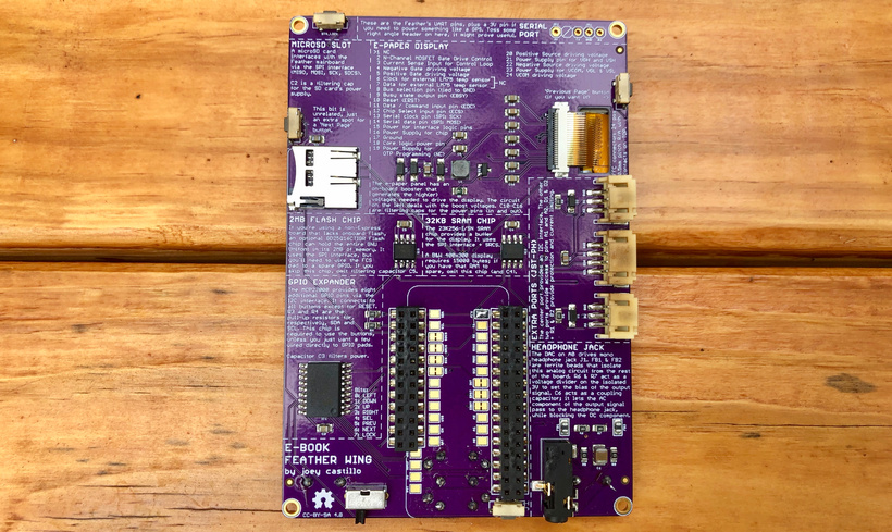
One rev later, this was basically the final revision of the e-book wing (the current one is A1-05 just to tweak the fit of the buttons). But around this time, I also recognized that the final answer likely wasn’t a Featherwing. The final answer was probably going to involve integrating the whole device into one gadget, a Feather itself.
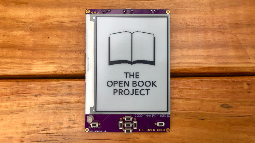
On top, the first prototype of the Open Book looks pretty good! But there were some issues that become apparent when you flip it over.
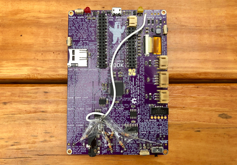
The obvious one is the big mess of tape at the bottom. For the buttons on the wing, I had been using a chip that provided something called “pull-up resistors”; these ensure that the buttons only become active when you press them. This time I moved to a new kind of chip that didn’t provide them, so the buttons didn’t work, and I had to tape these resistors on to test it out.
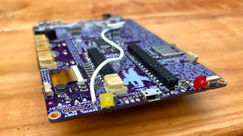
There were also some issues with through-hole components, big chunky LED’s that didn’t make a lot of sense. Another revision was needed.
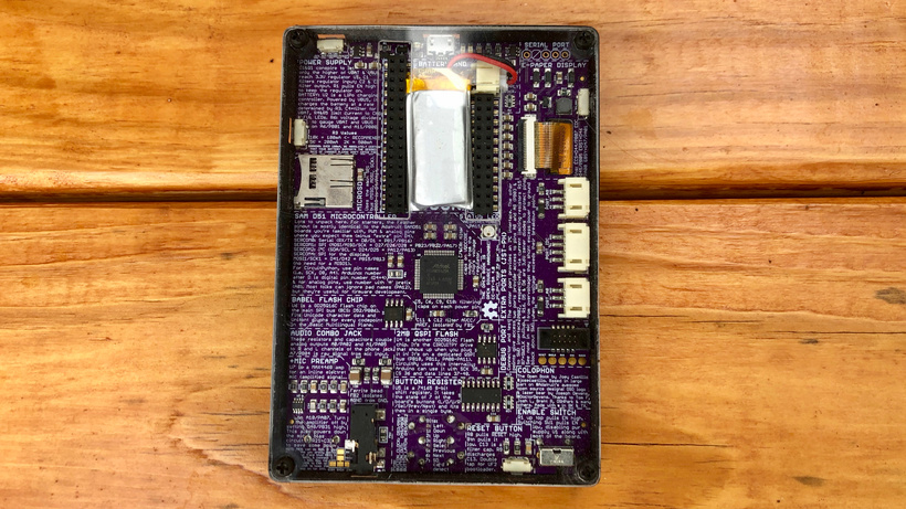
This is (almost) the final version of the Open Book. Pull-up resistors, surface mount LEDs, lots of tweaks and creature comforts. Still, in the end, pretty close to the original 3-D printed prototype from last year.
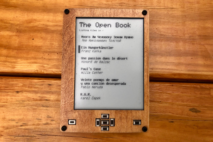
There’s one final revision published, to make the same tweak to the fit of the buttons, but it feels exciting to be at the far right side of the squiggle. Sales of the E-Book Wing boards are going well, and I’m hopeful I’ll be able to get a run of the Open Book boards made (to sell as bare PCB’s for folks to DIY).
In the immediate future, I’m splitting my time between more documentation for the book, and this new sensor concept that I’m playing with. More soon.