On bringing a new gadget to life
Originally published on Patreon.
I love the ritual of bringing up a new board. I love it when it works flawlessly. I love it when it fails catastrophically. I love it because it represents the answering of a question.
In the design phase you can build all sorts of castles in the sky; you can assign pins to purposes, wire it all up and weave elaborate stories about your power supply breathing life into your microcontroller, which will conduct a beautiful symphony with each of your peripherals playing a part.
Then you can build it, plug it in and hear it fail with an explosive POP!
“LOL does this work?” That’s the question that board bring-up answers.
I’ve had boards fail when a chip went boom and let out the magic smoke. I’ve also had boards whose failure mode involved me burning my finger on an overheated MOSFET, and I’ve even had one bringup that ended with me taking a pair of pliers to the fiberglass PCB to carve out a short on two internal layers.
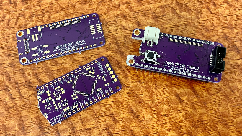
When it works it works, and when it doesn’t, there’s always something to learn. What’s not to love about that?
Sensor Watch Pro
Last week I started the process of bringing up the Sensor Watch Pro board. This board likely won’t be available until later this year — Fall if we’re lucky — but I have to start work on it now if I want to make that target date. It’s a more advanced version of the original Sensor Watch board, bringing some sensing capabilities onto the board itself, and improving on the features offered in the first version.
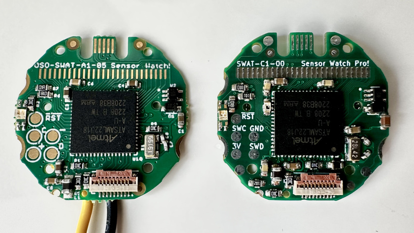
While these two boards might look similar, the fact is a ton of stuff had to change to make the board on the right possible. In order to accommodate the additional analog sensors — a temperature sensor and a light sensor — I had to shuffle a lot of pins around to find extra analog inputs. I also have vague hopes of making the LEDs brighter on this new version, which required some very specific pin assignments.
This meant shuffling almost all of the LCD pins, and reassigning two button inputs to pins that are normally reserved for debugging the device. This is an interesting choice! And at the design phase it definitely left me thinking “Is this going to work?”
I started answering that question last month when I assembled the board. The first bits were promising: I was able to test for shorts (none detected!) and power up the board with USB. Nothing blew up, and some prodding with the multimeter revealed 3.3 volts on the VCC rail. Flashed the bootloader, and lo, the WATCHBOOT drive appeared! A promising start.
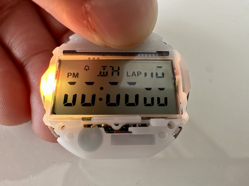
As of this month I’m at the point where I’m testing all the peripherals. Last week you saw the rainbow colored LED, and since then I’ve created a new board variant with the proper LCD pin assignments, and some tweaks to handle the new use of the debug pins. So far so good; in the image above, my test pattern is doing exactly what it’s supposed to do!
The next big item is going to be the light sensor, and that one is going to be a challenge. Reason: I not only want to use it for analog sensing of light levels, I also want to use it for communications. The light sensor is connected to a SERCOM peripheral on the L22, which is an interface capable of various kinds of serial communications. That includes the IrDA protocol, a data transfer method that uses infrared light.
Big “will this work” energy here: I’ve plugged nothing more than a phototransistor and a resistor into a microcontroller pin, in the hopes of receiving high-speed data via light shining through the front of a wristwatch. Now I have to throw together a transmitter of some kind, and find out whether it works.
If everything checks out, we’ll know the answer, and I’ll feel comfortable building this circuit 1,000 times over. The boards will go on Crowd Supply, folks will buy them and I will ship them, and we’ll put this board inside watches and onto wrists worldwide.
And if not, hey, there’s always revision 2.